
Medical Gas Pipeline Pressure Drop: Design Factors, Calculation and Prevention
10/14/20262 min read

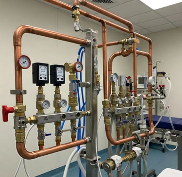
Why Pressure Drop Matters
Pressure drop is the reduction in gas pressure as medical gas moves from its source through the distribution system to a terminal unit. Some loss is unavoidable: gas encounters friction along pipe walls and resistance at fittings, valves, regulators and other components. The engineering objective is to keep pressure at every point of use within the applicable design and equipment requirements under expected operating conditions.
If losses are underestimated, outlets may receive inadequate pressure when demand rises. This can affect the performance of connected medical equipment and create operational concerns, particularly in areas with simultaneous demand. Conversely, simply choosing much larger pipes is not a complete solution: cost, space, flow velocity, system layout and applicable standards must also be considered.
Key Causes of Pressure Loss
Pipe diameter is a major factor. For a given flow, a smaller bore generally increases gas velocity and frictional loss, often substantially. Pipe material, internal condition and the gas’s physical properties also influence resistance. As a result, sizing calculations must use the relevant gas and design assumptions rather than treating all services as interchangeable.
Length matters as well. Engineers account for the actual straight-pipe route and the resistance of fittings and components. Bends, tees, reducers, valves and other items can be represented by equivalent pipe lengths or by resistance coefficients, depending on the calculation method. The resulting effective length may exceed the measured distance between the source and the most remote outlet.
Flow demand is equally important. A system must be evaluated for its design flow, not merely the average flow observed during quiet periods. Diversity and simultaneous-use assumptions influence the calculated demand: if several outlets are likely to operate at once, their combined requirements can create greater losses. Source pressure, regulator settings and losses through source or plant equipment also affect the pressure available to the distribution network.
Engineering Approach to Sizing
A typical design process identifies the gas services, source conditions, terminal requirements and applicable codes or standards. The engineer maps the network, determines design flow for each section, and evaluates the critical route to the most demanding or remote point. Pipe sizes are then checked against allowable pressure loss and other requirements, including velocity limits where applicable.
Calculation methods may use recognized fluid-flow relationships, such as Darcy–Weisbach, or validated methods and tools specified for medical gas design. These require appropriate inputs, including internal diameter, gas properties, flow, pipe roughness and the resistance of fittings. Pressure is not constant throughout a system, so the calculation should reflect operating conditions and the pressure available at the source.
Educational Example and Prevention
Consider a hypothetical branch serving several treatment spaces. A designer initially assesses only the straight-pipe distance and assumes one outlet will be used at a time. A fuller review adds the resistance of multiple bends and valves, uses a smaller pipe’s actual internal diameter, and accounts for simultaneous demand. The revised estimate shows a larger pressure loss along the critical route. The designer can then compare compliant options, such as revising pipe sizes or routing, and verify the result against project requirements. This illustration is educational only; it is not a substitute for project-specific calculations, coordination or review.
Good prevention starts with accurate drawings, realistic demand assumptions and complete accounting for fittings and equipment. Designers should coordinate with clinical, architectural and mechanical disciplines, verify source and regulator performance, and have calculations reviewed by qualified professionals. Installation quality, commissioning tests and documented verification are also essential. Final decisions must follow the governing standards, local requirements and the needs of the specific facility.
Services
© 2024. All rights reserved.
Products

We're Making it easier to find Better Medical Devices
Find us on Map:
Contact Information
Phone: +91 9029457428 | +91 9833236604 | +91 7506374381
Email : medevices2018@gmail.com | sales@medevices.in